indexmenu_n_3
Tactics
Links
-
Forum: Tactics plugin thread
Windows Download
To test Tactics_pi using VDR_pi nmea player.
OpenCPN Beta File Thingie 2.5.7 “rguser”, “rgpass” Go to Tactics directory and download download sample vdr file to play (Sample1.txt, Sample2.txt, Sample3.txt).

tactics_pi a performance enhancement to dashboard_pi
Rev 1.0

References:
1. Introduction
Everything started with the question : “Do we make it around the corner of that island when we tack now and sail the same apparent wind angle on the other tack ?“
Disclaimer :
This is still alpha code (not even beta), and you should not use it for
live – real sailing.
I will not be liable for any harm, damage or whatever strange things
happen if you use this plugin and rely on its data.
Table of Content
1. Introduction 1
1.1 What tactics_pi can do 3
1.2 Prerequisites 5
2. Basic functions work
without a polar file 5
2.1 Calculate true wind data 5
2.2 Calculate “Leeway” 6
2.3 Calculate the surface current
8
2.3.1 Activation of the current
display 9
2.4 Calculate and display
the boat laylines 9
2.5 Show wind barbs 10
2.5.1 Activation of Wind barb
display 11
2.6 Instruments 11
2.6.1 Current Direction and
Current Speed 11
2.6.2 Heel 12
2.6.3 Leeway 12
2.6.4 TWA to Waypoint 12
2.6.5 “App.&
True Wind Angle” dial instrument with TWD display 12
2.6.6 Average Wind Instrument 13
3. Performance
functions which need a polar file 14
3.1 Load a polar file 14
3.2 Display polar on chart 16
3.3 Activation of the
polar display on the chart 17
3.4 Performance data 18
3.5 Instruments which need a polar
18
3.5.1 Polarspeed 18
3.5.2 Actual VMG 19
3.5.3 Target VMG-Angle 19
3.5.4 Target VMG 19
3.5.5 Actual CMG 20
3.5.6 Target CMG Angle 20
3.5.7 Target CMG 20
3.5.8 Polar Performance 20
3.5.9 Bearing compass 21
3.5.10 Polar Compass 24
3.6 Temporary waypoint
and Target-TWA laylines 26
3.7
NKE style NMEA Performance Records and export to the instruments 28
3.8 Settings in the INI file 31
3.9 Restrictions/known
issues at the time being 34
4. Terminology 34
5. Appendix 35
5.1 How to
align/check your magnetic compass with O 35
6. History 36
1.1 What tactics_pi can do :
To sail Target-VMG / Target-CMG angle, simply steer the blue HDT pointer on one of the Target-VMG / - CMG markers.
As you can see here, there may be 2 red CMG markers, the preferred one has the biggersize !
-
Calculate true wind data : TWA, TWD, TWS from true heading (HDT), speed through water (STW) and app. Wind speed (AWS), with optional correction by heel-angle. Calculation is enabled via a preference setting and disables available true wind data from the bus throughout the tactics_pi plugin.
-
Calculate the “leeway”, the boat drift based on heel. A common formula is used for that purpose.
-
Calculate the surface sea current and display it as single instruments (current speed/direction) as part of the “Bearing compass” or as overlay on the chart (semi transparent). The routines take boat heel and leeway into account. If you don’t have a heel sensor, there is a simply workaround, see below. Current display on the chart can be disabled by a preference setting.
-
Calculate and display the boat laylines for the current tack, and the same TWA on the other tack. Sea current is taken into account, if available ! Laylines may be toggled on/off. Adjustable length and max. width (triangle, with one corner at the boat) of the boat laylines. The layline width reflects the boat’s yawing (COG changes over time).
-
Load a polar file and calculate/display performance data, like actual VMG (velocity made good up-/downwind), Target-VMG, Target-TWA (the opt. TWA up-/downwind), CMG (course made good towards a waypoint), Target-CMG (opt. CMG angle and speed), polar speed (the speed you should be able to sail at current TWA/TWS based on your polar),…
-
Display the actual polar as overlay on the chart, including markers for Target-VMG/CMG angles. Just adopt your course and place your heading pointer on one of the markers, and you sail Target-VMG/CMG based on your polar …
-
Set a (one !) temporary tactics waypoint and display the laylines to the mark, based on a Target-TWA calculation, while taking your polar into account.
-
It has a “dial instruments” called “Bearing compass”. Boat true heading (HDT) points “up”, it shows the boat laylines as well, the surface current, a pointer to the waypoint (either set manually as the temporary Tactics waypoint or read from a NMEA RMB sentence), needles for AWA and TWA, markers for the Target-VMG/CMG angles.
-
It has a “Polar compass” instrument, graphically displaying the actual polar ring and markers for Bearing to WP, Target-VMG angles and Target-CMG angles.
-
It has an “Average Wind” instrument with an adjustable averaging time, which displays graphically the average wind and its deviations to port / starboard
-
It can create specific NMEA performance records with the purpose to export them to the displays of your instruments. You can now e.g. calculate the polar target speed in the plugin and send it to your instrument display outside in the cockpit. Currently only available for NKE, but may be enhanced in the future.
-
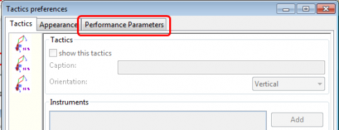
There are various settings, which I grouped in a separate tab. To access the preferences screen, right mouse click on the tactics_pi window, then select “Preferences …”
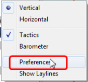
You’ll find all seetings in a separate tab “Performance Parameters”
:
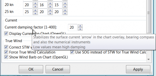
There are so-called ToolTips available for almost all of the
preferences. Just hover the mouse over one of the prefs:
1.2 Prerequisites :
Required
-
You will need to activate OpenGL, if you want to use the chart overlay functions.
-
SOG, COG from the GPS
-
Preferably True Heading from an electronic compass.
-
if not available, magnetic heading will do, as long as you have magnetic
variance available (either from the GPS RMC sentence or from the wmm_pi plugin)
-
Boat speed through water from a log / “paddlewheel” sensor
-
Apparent wind angle and apparent wind speed
-
Heel sensor which supplies your boat heel angle to Oas XDR sentence
If not available, there’s a workaround with manual input
-
You need a polar file of your boat to use all polar based performance calculations
-
Calibrate AWA, Compass HDG/HDT, STW (Speed through water), and AWS (apparent wind speed) as good as possible.
-
Especially the compass heading calibration tends to be neglected. But this is vital for a proper surface current calculation. All I can say is : sh* in – sh* out …

See also the Terminology at the very end for explanation of terms
2. Basic functions work without a polar file
+
2.1 Calculate true wind data
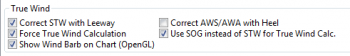
The plugin can calculate true wind data (TWA, TWS, TWD) but keeps the calculated data inside the plugin (it does not broadcast it to O)! True wind calculation is done silently if you don’t have TWA, TWS, TWD available in your NMEA stream. Furthermore you can force the true wind calculation in the plugin by a preference setting. If the tick “Force True Wind Calculation” is set.
-
It does not matter if TWA, TWS and TWD are already available on the system or not. Calculation is done in the plugin then. It does calculate TWA, TWS and TWD.
-
This is e.g. useful, if you have a heel sensor, which is not integrated in your instrument bus. You can use the corrections then to get more accurate true wind data.
-
Input is AWA, AWS, STW, and for TWD also true heading HDT.
If you don’t have HDT on your system bus (but only HDG), you can use wmm_pi.
-
wmm_pi supplies the magnetic variation and if running is taken into account to calculate HDT from HDG
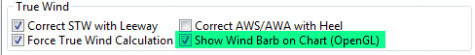
If you have a heel sensor in your system, and its data is available in O, you can use two corrections.
Correct STW with Leeway:
The plugin can calculate your leeway (drift angle) based on on your heel sensor (see below). That means your boat is possibly moving sideways, which adds an error to the True Wind calculation. Standard instruments normally do not take this effect into account, as far as I know. NKE does this correction in its regatta processor only, but not on their normal instruments.
Correct AWS/AWA with Heel:
This option corrects your AWS and AWA data by the heel angle. Use this option with great care !. Manufacturers normally already do correct this, if you have a heel sensor integrated in your instrument bus. O will simply receive the already corrected data for AWS / AWA then. The result would be wrong data ! I implemented this option for those sailors using an external (or DIY) heel sensor, which is not recognized by their instrument system. You’ll get a warning popup as soon as you set the tick.
Use SOG instead of STW for True Wind Calc:
Replaces STW (Speed through water, the “log”) with SOG (from the GPS) in the internal true wind calculation. The idea is simply to have a fallback for the true wind calculation in case your log fails and also to eliminate side effects on the calculation by surface current.
+
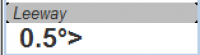
2.2 Calculate “Leeway”
Leeway describes the drift of the boat due to the force of the wind.
Leeway is the basic input for the surface current calculation described
later on. Input for the leeway calculation is your heel angle. Normally
you’d say : the more you heel, the more you drift . But that’s only part
of the truth. Other significant inputs are boat speed and the shape of
your hull…
A widely (NKE, B&G,…) used formula calculates the leeway with 3 input values : heel, boat speed (STW), and hullshape-factor.
-
Leeway = hullshape-factor*heel/(STW*STW)
To make this work, you have to estimate the hullshape-factor.
The attribute in the preferences is called “Boat’s Leeway factor
[0..20]:”
-
The input range is 0…20, 10 is a good value to start with.
If you don’t have a heel sensor on board, you can either set a fixed value ( e.g. 0 when motoring without sails), or try to set up a very simple “heel polar”.
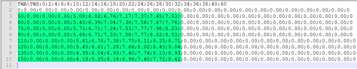
Heel polar:
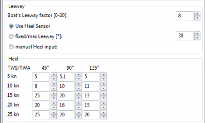
The idea is that almost every magnetic compass installed in the cockpits has a scale, where you can read the degrees of heel.
Then simply compare the O instruments display, for TWA and TWS, read the values from the scale and put it into the small table above.
Please be sure to read True Wind Angle and True Wind Speed and not apparent wind angle and speed !!!
I tried it on my own boat, comparing the heel polar values with those of my sensor. It works astonishingly well.
Even if you use the heel-polar, you have to estimate the “Boat’s Leeway factor [0..20]:”
You have 3 choices for heel input, depending on where you set the radio button in the preferences. You can switch the radio buttons forth and back while sailing to compare the results, no problem
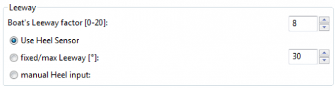
The attribute “fixed/max Leeway [°]:” is dual purpose:
-
The given value is always taken into account as maximum possible Leeway value.In the screenshot below, I set it to 30°. If your heel polar or calculation with the formula above outputs values >30°, the program takes 30°.
-
If you set the radio button here, the routines always take 30°, no matter what your sensor calculates or your heel-polar would tell you.
2.3 Calculate the surface current
If you compare your HDT and COG vectors in O (the 2 forward vectors on the chart at your boat), the difference between both is a mixture between Leeway (the boat’s drift) and surface current. Once we can determine Leeway, the rest is surface current.
The surface current calculation is simply a triangle calculation with vectors.
-
Always seen from the current position, the first vector is HDT (degrees) / STW (length).
-
As your boat drifts with the wind, the second vector is “course through water” (CRS, degrees) and STW (length)
-
“course through water” is actually HDT with applied leeway.
The resulting vector between CRS/STW and COG/SOG is the surface
current.

To calculate the current, you need as input HDT, STW, Leeway, COG and SOG and your GPS latitude / longitude.
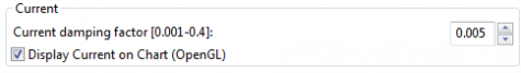
In the preferences you can set 2 options for the current :
-
the damping factor : the lower the values are the more filtering is applied, and the reading gets more stable. On the other hand, it starts lagging a bit.
-
The lower the value, the more damping is applied. Actually I’m experimenting in the range of 0.001 to 0.025. Keep this value at the lower end, the start to increase, until it gets unstable.
+
2.3.1 Activation of the current display
You can show a semi transparent blue current symbol underneath your boat, showing the surface current direction.
To activate the current display on the chart by default, upon program start, navigate to the Preferences dialogue and set the tick “Display Current on Chart (OpenGL)”. The preference is only setting the default.
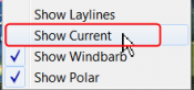
While navigating in OpenCPN, you can turn the current overlay display on / off as you like.
Just right-click on any Tactics_pi instrument and select “Show *C*urrent”. This toggles the display on/off.
+
2.4 Calculate and display the boat laylines
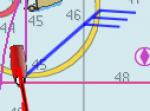
You can show the boat laylines on the chart. They refer to COG.
The colours mean
-
red = wind from port
-
green = wind from starboard.
The width is defined by the yawing of your boat, the more you yaw, the wider they get
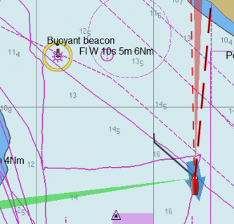
The second layline (green in this example) simply shows you where you would get on the other tack / gybe when you sail the same TWA after the tack. Leeway and current are taken into accountfor the calculation of the second layline. In the preferences, you can set the following options :
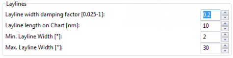
The Layline width damping factor is the rate how fast the layline width reacts on COG changes.
It’s done with exponential smoothing, the smaller the factor, the higher the damping rate.
You can define the length of the laylines on the chart, as well as a minimum and maximum width.
If you don’t like the yawing effect simply set min and max both to 1 or 2 degrees.
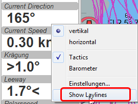
To toggle the layline display on the chart on/off, right-click on the tactics_pi main window and select “Show laylines”
+
2.5 Show wind barbs
You can also show a wind barb at the boat position, showing you direction and speed (feather length) in 5 kt steps
+
2.5.1 Activation of Wind barb display
To activate the wind barb display on the chart by default, upon program start, navigate to the Preferences dialogue and set the tick “Display Wind Barb on Chart (OpenGL)”. The preference is only setting the default.
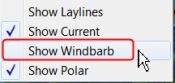
While navigating in OpenCPN, you can turn the wind barb overlay display on / off as you like. Just right-click on any Tactics_pi instrument and select “Show Windbarb”. This toggles the display on/off.
I took the basic code for the wind barbs from the tack and laylines plugin, but had to adopt the transit from one barb to the next level. Furthermore it to show the barbs up to 47 knots correctly now (it ends at 30 kts in the original code)
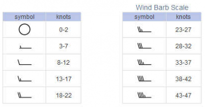
This is the currently implemented wind barb scale (0-2kts has no feather at all) :
2.6 Instruments :
+
2.6.4 TWA to Waypoint
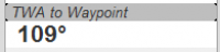
It’s meant to do a quick check of the TWA on the (new) tack prior to
sailing the tack/gybe maneuver.
Either place a WP in the GPS( NMEA–> RMB) or simply drop the TacticsWP
on the new course line.
As with the other functions, the “Tactics temp.WP” overrules the RMB
coming in from a GPS.
It should give you an idea which gennaker/spi or sail to select on the
next tack.
+
2.6.5 “App.& True Wind Angle” dial instrument with TWD display
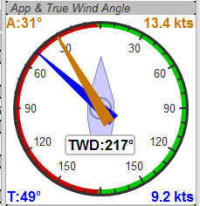
I added the TWD to the dial instrument; this saves some space on the screen for an extra instrument
+
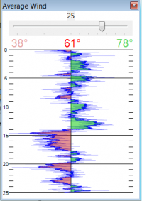
2.6.6 Average Wind Instrument
 .
. . .
.
. . .
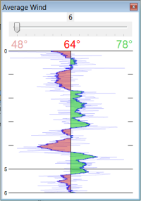
I created a new graphical instrument which shows the average wind and its deviations to both sides.
The curve is centered on the average wind, green means the wind is on starboard of the actual average wind, red means it blows more from port.
You can adjust the averaging time in steps of 1 [min] between 6 and 30 mins.
The red number in the center is the average wind direction, left and right is the min and max (unfiltered) wind angles to either side.
The very thin lines are the unfiltered wind direction input from the instruments.
To adjust the time average, just pull the slider left / right.
The vertical scale is [minutes], short dashes every minute, full horizontal line every 5 minutes.
The instrument has its own timer, so it’s independent of the connection speed.
The idea is:
if you sail in puffy, changing winds, that you see graphically when the wind changes to the other side. In theory, you should tack, as soon as the wind veers away and crosses the average wind direction …
As you can see in the examples above there are definitely cycles, where the wind changes direction.
+
3. Performance functions which need a polar file
+
3.1 Load a polar file
You can load a polar file from the preferences screen
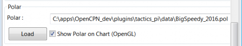
Click on the load button and select a polar file.
The format is the same that polar_pi uses (or better: used last summer). I took the basic code from there, to keep the plugins consistent. This is also the reason why I did not spend time in displaying the polar again. You can use polar_pi instead.
When loading the polar, it is written to a 2 dimensional static array with 181 lines for each TWA degree (0…180°) and 61 rows (0…60) for each knot of windspeed. It’s a simple lookup table for the latter use, with the purpose to reduce the processor load and increase access speed in normal use.
Loading Procedure :
-
The whole array is prefilled with NAN values.
-
The values from the polar file are placed at their corresponding spots in the array
-
The missing data in between given values (= not NAN) is then filled with average values.
Please note :
-
Only polars with TWA / TWS / STW, and TWS/STW in knots make sense
-
I do not extrapolate polars beyond their outside limits. If you run in a 30kt wind, and your polar ends at 25 kts, then the performance instruments will give you a “no polar data” text. I suggest that you turn polar_pi / vdr_pi on at that point and record your data

The only exception of the extrapolation is the range between the 0 kts windspeed and the first given value.
I do simple averaging here.
In other words : if yellow is the whole polar from TWS 0-60 kts and TWA 0-180°prefilled with NAN, and red is your polar data, you will get the green square filled with data.

See the ini file chapter, how you can read out the array as a text file (see key PolarLookupTableOutputFile=…).
Here is an example of a polar file starting at 50° TWA
And this is the corresponding lookup table dumped to a file using the ini key PolarLookupTableOutputFile
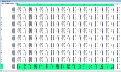
True wind speed values are averaged now. True wind angle is still rounded to the next full knot. For testing I implemented full averaging of TWS &TWA as well , but live comparisons didn’t show improvement. I think this is a good compromise to average TWS only, as I’m pretty sure that TWA won’t be more accurate than one knot, due tu upwash issues, position and accuracy of the wind vane, compass accuracy, etc.
+
3.2 Display polar on chart
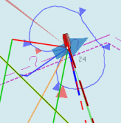
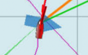
You can display the polar as overlay on the chart.. The size of the different polar “rings” is normalized, they all have the same size. Nevertheless, the plugin always shows the current / correct polar ring. The polar orientation is related to the true wind direction, and it shows blue markers for the Target-VMG angles up- and downwind, and red markers for the Target-CMG angles (if you have an active NMEA-RMB-sentence or a Tactics_pi waypoint set).
There’s also a small blue HDT line diplayed. I decided to add an additional marker for Hdt, because I found it easier than always remembering which of the 2 red default markers is Heading and which one is Course over ground …
To sail Target-VMG / Target-CMG angle, simply steer the blue HDT pointer on one of the Target-VMG / - CMG markers.
As you can see here, there may be 2 red CMG markers, the preferred one has the biggersize !
+
3.3 Activation of the polar display on the chart
To activate the polar display on the chart by default, upon program start, navigate to the Preferences dialogue and set the tick “Show polar on chart (OpenGL)”. The preference is only setting the default.
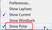
While navigating in OpenCPN, you can turn the polar overlay display on / off as you like.
Just right-click on any Tactics_pi instrument and select “Show Polar”. This toggles the display on/off.
+
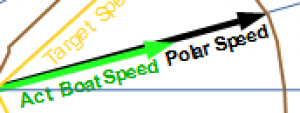
3.4 Performance data
various performance data is available as text instruments. See the following chart for reference on the different terms in relation to a polar curve

For some of the instruments I split the display in a % value for your current speed in relation of the polar data value as 100%.

In this example, we’re currently doing (only) 51%, of what the polar has stored as optimum value. According to the polar we should be able to do 11.95 knots.
The reason to do so was simply that the data belongs together anyway and so to save space on the screen
+
3.5 Instruments which need a polar
+
3.5.1 Polarspeed :
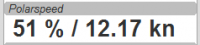
This is simply the reference of what speed we should be able to sail based on our current TWA / TWS values. The % value is the reference to STW.
This is actual boat speed versus polar speed in the drawing above.
Values below 100% mean, where slower than the polar says, above 100%
mean where faster than the polar (we should run vdr_pi now to record the
data) ![]()
Useful in crosswind / reaching conditions without a waypoint
It shows the optimum speed for the given wind conditions.
+
3.5.2 Actual VMG :
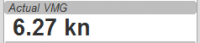
Is the “Velocity made good” refering to the wind direction. The means we’re moving with 6,27 kts into wind direction. Also works when we sail downwind (then it’s off the wind)
VMG = STW * cosine (True Wind Angle)
+
3.5.3 Target VMG-Angle :
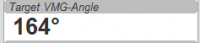
Also known as Target TWA;this is the optimum TWA (True Wind Angle) when sailing upwind or downwind for a given wind speed, based on your polar data. Very useful when sailing up-/downwind without a waypoint.
The program simply searches the polar with a given TWS for the optimum TWA up-/downwind. It’s defined as the tangens on the polar.
+
3.5.4 Target VMG :
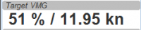
Also known as “target boat speed” (target speed in the diagram above)
This is the reference to the Target VMG-Angle. In our example it means :
If we would sail with 164° TWA (from ex. above), then we could make 11.95 knots according polar), but currently we’re doing only 51% of that.
+
3.5.5 Actual CMG:
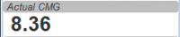
Actual Course Made Good = aka VMC; the component of your boat speed towards a waypoint. We’re moving with 8.36 knots towards a waypoint

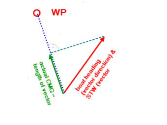
CMG = STW * cosine (Heading - Marks bearing)
Quite valuable on reaching courses towards a waypoint.
+
3.5.6 Target CMG Angle :
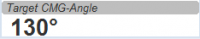
Optimum angle to sail fastest to a waypoint, based on your polar data (Like VMG, but not up-/downwind but towards a waypoint).
+
3.5.7 Target CMG :
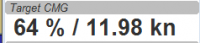
Same as Target VMG, but towards a waypoint. Means : “If we would sail 130° (Target CMG Angle, from ex. Above), we would move towards the waypoint with 11.98 knots, but currently we’re only doing 64% of that.
Comment : Calculation is verified, but it doesn’t tell you (yet) if you’re on the correct tack
+
3.5.8 Polar Performance
– sail trimming aid –
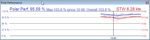
A new graphical instrument like Wind-History or Baro-History.
It simply plots the STW (speed through water) as percentage of the polar speed data (=100%) for the actual true wind speed TWS and true wind angle TWA. It is this comparison in the polar chart above, plotted as %

The idea is a simple sail trimming aid, as the percentage value is quite stable in comparison to the real speed values. And TWA / TWS is constantly adjusted while reading the polar data.
Message : as long as the filtered curve points upwards your trim adjustments were right, if it points down, you’re sailing worse than before …
Comment : Still needs probably adjustments with the damping factor, # of points plotted, etc.
+
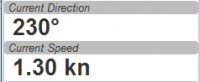
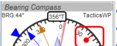
3.5.9 Bearing compass
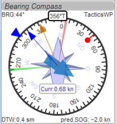
Nice dial instrument, inspired by NKEs tactics page, which I called Bearing Compass.
UP- direction is HDT, in this example (356°T)

Surface Current:
We see the blue surface current arrow based on boat heading (HDT) and the current speed “Curr: 0.68 kn”

Needles for TWA and AWA :
Furthermore we have the blue, thin arrow, which is TWA on boat axis. It
also shows the TWD on the degree scale (315°) and the AWA arrow in
orange/yellow (standard dashboard colour)
Laylines :
You see the red/green laylines, which are based on COG. As with the laylines on the chart,
the second layline shows you where you end up sailing the same TWA on the other tack.
Leeway and current are taken into account.
Use the second layline together with the waypoint marker described below.
Please note : the calculation is based on TWA. Especially when sailing downwind with a gennaker, your apparent wind angle depends very much on the speed of the boat. As soon as the gennaker start working aerodynamically, it’ll speed up the boat and your AWA will show lower values (points more foreward). If you gybe now, your boat speed will drop, and although sailing the same TWA, your app. wind angle will be higher than before. You will have to bring you boat back up to speed to see the same AWA than before the tack.
This can be tricky when you’re close to a buoy and don’t have much space/time to speed up your boat again.
Target VMG Angle indicator :
The blue triangle outside the degree scale is the Target-VMG Angle
(Target TWA)
Simply adopt your course to place your blue TWA-arrow on the Target-VMG
pointer, and you sail optimum (polar based) speed up-/or downwind.
Waypoint marker :
If a waypoint is active, either by a NMEA-RMB sentence from your GPS or the temporary tactics WP which you can place on the chart, you will see the WP as a red dot.
The manually placed tactics WP overrules a parallel available RMB
sentence
Change your course and place it under the layline ( the red one in this
example) and you will directly bump into it.
Or use the second layline to determine when it is time to tack towards the waypoint and when you will make it around the WP (the red dot should be outside the second layline then)
Additional data :
The top 2 corners show the bearing to the WP and the name of the WP (See screenshot above).
The lower 2 corners give you
DTW = the distance to the WP and predicted speed over ground on the
other tack, assuming that you sail the same TWA on the other tack.
This simply drops out of the surface current calculation …
+
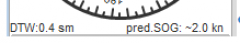
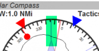
3.5.10 Polar Compass
I derived this instrument from Bearing Compass. Once you loaded a polar,
it shows you the actual polar ring. The size of the ring is normalized
(always the same size).
The polar is rotated with the TWD, which is shown as thin blue line
here. In this example True Wind Direction is ~226°, the wind is blowing
from port aft. Please note the vertical True Heading line, highlighted
in green here :
The 4 blue markers (triangles) are showing the Target-VMG-Angles up- and
downwind. They are based on the actual polar ring and are moving with
the with the polar.
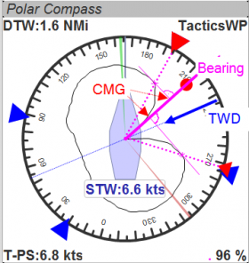
The red maker(s) (triangles) are the Target-CMG Angles towards a Waypoint. They are only shown if you have an active Waypoint set (via NMEA-RMB or the ‘temp. TacticsWP’).
The red dot inside the compass shows the bearing to the waypoint.
In contrary to Bearing Compass, the VMG/CMG markers are shown in conjunction with the polar and are rotating with the polar/true wind angle.
To sail optimum VMG- or CMG-Angle, change your course in a way that the
boats heading line (green markup above) points on one of the
markers.
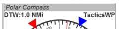
Top left and right data fields show
-
DTW = Distance to Waypoint
-
Waypoint name (here : TacticsWP)
-
The centered data is STW = Speed Through Water
 +
 +
image:manual/plugins/tactics/tactics_pi_html_1af9edc485342ace.png[image,width=240] +
 +
The 2 bottom fields are
-
T-PS : Target-PolarSpeed on the left
-
PolarSpeed-% = the percentage of you actual STW compared to the Target-PolarSpeed.
Furthermore you see the laylines which are based on CoG.
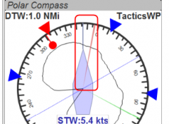
In this example, there is a angle btw. the HDT line and the layline, so
we have a significant drift !
There may be 2 red CMG pointers, based on Bearing and True Wind direction. Generally one of them is preferred, because you approach the WP faster. The preferred one has a bigger size !!!
*For those who are interested in the theory of CMG calculation*, see the following example with the markups below:
We have TWD, shown with the bluearrow. The polar is rotated with TWD.
Next we have the bearing to our WP, see the solid purple line “Bearing”.
From this solid purple bearing line, we have to find the tangens on the
polar curve to both sides. The tangens is – in relation to the purple
bearing line – the highest point of the polar curve. Graphically one
draws perpendicular lines from the purple bearing line to either side
until it just touches the polar curve. The length on the purple bearing
line, measured from the 0-point of the polar, to the perpendicular
intersections (marked CMG) corresponds to the Target CMG speed.
+
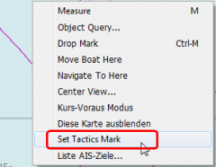
3.6 Temporary waypoint and Target-TWA laylines
You can right-click on any place in the chart and drop a temporary waypoint (exactly one).
As soon as you activate the layline display, the plugin will do a Target-TWA calculation to that WP, based on the current TWD and your boat polar. Surface current is taken into account.
-
You can delete that waypoint as any other WP. Select it with right click and choose “Delete”.
-
You can drag the waypoint on the chart, it behaves like a normal waypoint.
-
Depending on your settings in O you may have to open the WP properties to drag.
-
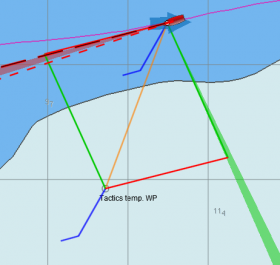
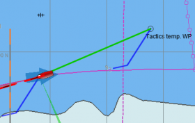
Currently it takes the Target-VMG (Target-TWA) angle up-/downwind and applies it to our boat as well as to the mark (Tactics temp. WP).
-
If there is a line intersection, it chops off the lines at the intersection, et voilà …. Colours green and red are again the wind directions green = wind from starboard, red = wind from port
Additionally
-
I do a polar based calculation to see if the direct course would be faster compared to the Target-VMG calculation.
 .
. .
.
.
. .
.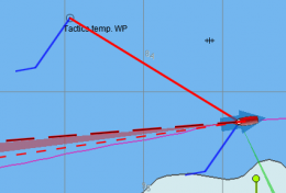
In that case you’ll get a red or green line directly to the waypoint. Colour depends on the side the wind is blowing from. Wind from port → red, wind from starboard → green As you can see here I’m placing a wind barb also on the tactics waypoint.
Please note :
-
In contrast to weather routing, I’m explicitly not using grib files here for current/wind info.
-
The “Temp. Tactics Waypoint” is meant for a quick, near run around a buoy, cape of an island, etc. using the live wind data we currently experience and the momentary surface current.
-
Just drop a mark on the chart and off you go. Delete it, drop it somewhere else, and boom, off you go again. Maximum one tack/gybe not more.
+
3.7 NKE style NMEA Performance Records and export to the instruments
NKE supports the upload of specific performance data to their instrument bus, which can be shown in their displays then. These records are polar based and unless you’re using their (quite expensive) regatta processor, this gives us an easy way to display e.g. the “Target Polar Speed” outside in the cockpit on the standard instrument displays.
-
Due to the lack of information on other manufacturers capabilities, I implemented this for the NKE system right now.
-
Be aware that OpenCPN can only import/export NMEA183 right now, but not NMEA2000 or SeaTalk.
The following 5 records are implemented :
Speed and performance target
$PNKEP,01,x.x,N,x.x,K*hh<CR><LF>
          |      \ target speed in km/h
           \ target speed in knots
Course on next tack
$PNKEP,02,x.x*hh<CR><LF>
           \ Course (COG) on other tack from 0 to 359°
Opt. VMG angle and performance up and downwind
$PNKEP,03,x.x,x.x,x.x*hh<CR><LF>
          |   |    \ performance downwind from 0 to 99%
           \   \ performance upwind from 0 to 99%
            \ opt. VMG angle 0 à 359°
Angles to optimise CMG and VMG and corresponding gain (available but to be verified)
$PNKEP,04,x.x,x.x,x.x,x.x*hh<CR><LF>
          |   |   |    \ Gain VMG from 0 to 999%
           \   \   \ Angle to optimise VMG from 0 to 359°
            \   \ Gain CMG from 0 to 999%
             \ Angle to optimise CMG from 0 to 359°
Direction and speed of sea current
$PNKEP,05,x.x,x.x,N,x.x,K*hh<CR><LF>
          |    \     \current speed in km/h
           \    \ current speed in knots
            \ current direction from 0 à 359°
There is a new tab now in the Preferences where you can define up to 5 performance NMEA183 records to be created.

These 5 NMEA183-records all begin with $PNKEP and are created on the fly using the data calculated in the plugin and are sent to OpenCPNs NMEA stream. To send the records to your instruments, you have to define an outgoing connection in you Interface connections, e.g. like this :

-
Set an output filter as shown above, filtering for PNKEP.
-
After set up, you should see records beginning whith $PNKEP, in your NMEA debug window.
NKE exports the $PNKEP sentences as soon as they’re available on the topline bus. Normally they’re calculated in their regatta processor and then exported to the PC.
-
Therefore ignore all incoming $PNKEP sentences !
Click on Input filtering (see screenshot above), select Ignore sentences and add PNKEP. -
Don’t forget to re-init your NMEA data stream in your instruments, to make sure the new records are accepted.
+
3.8 Settings in the INI file
I added a complete tab “Performance parameters” with all the settings

-
The Apply button set the global variables which are used for the preferences directly, without closing the pref’s window.
-
All parameters are written to the opencpn.ini file using the standard “dashboard” functionality, i.e. when closing tactics_pi itself.
-
I’ll add a “Save” button here, which directly writes to the ini file.
You’ll find all keys under section [PlugIns/Tactics] and subsequent
sections starting with [PlugIns/Tactics/…]
The basic setup is inherited from dashboard_pi, I did not change any of
the “original dashboard” keys, but added some
Relevant are :
**[PlugIns/Tactics]**…
  * CurrentDampingFactor=0.003
  * MinLaylineWidth=2
  * MaxLaylineWidth=30
  * LaylineWidthDampingFactor=0.2
  * ShowCurrentOnChart=1
  * LaylineLenghtonChart=5
**[PlugIns/Tactics/BearingCompass]**
  * DampingDeltaCoG=0.4
  * MinLaylineDegrees=2
  * MaxLaylineDegrees=30
**[PlugIns/Tactics/Performance]**
  * PolarFile=C:\\apps\\OpenCPN 4.1.925\\plugins\\weather_routing_pi\\data\\polars\\Aki950routage.pol
  * PolarLookupTableOutputFile=C:\\temp\\Polar.txt
  * BoatLeewayFactor=8
  * fixedLeeway=30
  * UseHeelSensor=1
  * UseFixedLeeway=0
  * UseManHeelInput=0
  * UseSOGforTWCalc=1
  * Heel_5kn_45Degree=5
  * Heel_5kn_90Degree=5
  * Heel_5kn_135Degree=10
  * Heel_10kn_45Degree=8
  * Heel_10kn_90Degree=10
  * Heel_10kn_135Degree=11
  * Heel_15kn_45Degree=25
  * Heel_15kn_90Degree=20
  * Heel_15kn_135Degree=13
  * Heel_20kn_45Degree=20
  * Heel_20kn_90Degree=16
  * Heel_20kn_135Degree=15
  * Heel_25kn_45Degree=25
  * Heel_25kn_90Degree=20
  * Heel_25kn_135Degree=20
  * UseSOGforTWCalc=1
  * ExpPolarSpeed=1
  * ExpCourseOtherTack=0
  * ExpTargetVMG=1
  * ExpVMG_CMG_Diff_Gain=0
  * ExpCurrent
I think they are selfexplaining, if you compare the settings with the
preferences screenshot above.
-
All damping factors are “alpha” from the standard exponential smoothing formula, except CurrentDampingFactorwhere I’m using double exponential smoothing at the moment.
-
They should range between something above 0 and 1, the smaller the number, the higher the damping, 1 means no filtering at all
Recommendation :
-
Use CurrentDampingFactorwith low values, like 0.03 to get a stable reading
-
One interesting key, which is not available in the preferences screen is PolarLookupTableOutputFile
-
As explained earlier, the polar file is loaded into an array. When you set this key, you can dump that array to a (tab delimited) text file, which can be read e.g. with notepad++.
-
As mentioned earlier, this array is prefilled with NAN values, NANs are reflected in the file as “-1.#J”.
-
If you want to see/check that, just add that key manually under section [PlugIns/Tactics/Performance]
Make sure the path exists and the given file is writeable. There’s no
safety checks implemented here, so use at your own risk.
There are more keys and sections for tactics_pi but all others came with
dashboard_pi and were not touched by me.
+
4. Terminology
[.np_break]# #
| Term | Description |
|---|---|
AWA |
Apparent Wind Angle; the relative wind angle measured
by |
AWS |
Apparent Wind Speed; the relative speed of the wind |
CMG |
Course Made Good; the speed approaching a waypoint |
COG |
Course Over Ground; generally supplied by the GPS |
HDG |
Magnetic heading of your compass; not compensated |
HDT |
True heading of your compass. “True” means compensated |
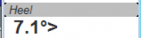
Heel |
The angular degrees how your boat is heeled (leaning) |
CRS |
Course through water; HDT + Leeway, but without currents |
Leeway |
The drift of your boat based on the wind. As soon as the |
SOG |
Speed Over Ground; generally supplied by the GPS |
STW |
Speed Through Water; the info that is returned by |
Target CMG |
The optimum speed / angle towards a waypoint; aka VMC |
Target VMG |
The optimum speed / angle up- or downwind with reference |
TWA |
True Wind Angle; the angle of the true wind relative |
TWD |
True Wind Direction; true wind direction related to |
TWS |
True Wind Speed; the speed of the wind in the atmosphere |
VMC |
Velocity Made on Course; same as CMG |
VMG |
Velocity Made Good; the speed up-downwind with |
[.np_break]# #
+
5. Appendix
5.1 How to align/check your magnetic compass with O
-
Swing your compass as described by the manufacturer
-
Connect your GPS to O to get a stable position
-
Make sure you have true heading available (use wmm_pi, in case you don’t get the mag. variation from the GPS)
-
Directly in O, set your heading predictor to a high value, e.g. 10 miles
-
Put the mouse onto the (thin HDT) preditor line towards the end of the line (the long line reduces the error)
-
Simply compare now true heading with the status line or the “From Ownship” display…
-
Then adjust your compass (in this case : -1°)
That’s it…
+
6. History
[.np_break]# #
| Rev | Date | Remark |
|---|---|---|
1.0 |
24.05.2016 |
Initial release |
1.1 |
24.05.2016 |
Corrected description of true wind calculation |
1.2 |
25.05.2016 |
Wind barbs corrected; steps corrected and enhanced up to 45kts |
1.3 |
07.06.2016 |
“TWA to Waypoint” instrument implemented |
0.4 |
11.06.2016 |
Laylines-to-waypoint reworked, documentation updated |
0.5 |
14.06.2016 |
Preferences with scrollbar, internal icons updated |
0.6 |
27.06.2016 |
Added TWD to the “App. & True Wind Angle” dial
instrument; |
0.7 |
04.07.2016 |
Polarspeed, Target-VMG, Target-CMG, Target-CMG Angle |
0.7.3 |
16.07.2016 |
User settings for wind / boat speed implemented |
0.8 |
06.11.2016 |
Correction of TWD calculation |
0.9 |
04.12.2016 |
Completion of $PNKEP records |
1.0 |
07.01.2017 |
Polar compass |
[.np_break]# #
+
7. Tactics FAQ
Why bother with Speedo Paddlewheels? Here is a good discussion
What are the differences between Ground, Apparent and True Wind Direction? More Good Discussion
You should also read this chapter in the B&G Essential Guide to Sailing Instruments, page 8 titled “Why can’t I use SOG and COG for calculating True Wind?”
Good technical basis, useful for OpenCPN work: Wind Triangle.pdf
Sailingworld.com Decoding your electronics readings If there is any current, the use of SOG instead of STW will be very inaccurate.
